necessary. The method of calculation also changes so that we may
determine the actual tension at the hold-down position.
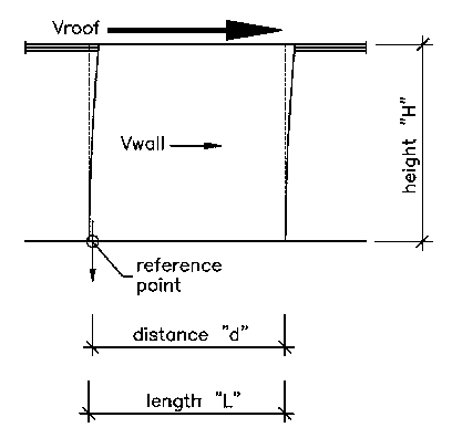
Distance "d" depends on the size of the end stud or post
and the
bolt centerline in the hold-down.
| Basic Shear Wall Diagram | |
 |
|
| This third example presents the first case where
a hold-down is necessary. The method of calculation also changes so that we may determine the actual tension at the hold-down position.
Distance "d" depends on the size of the end stud or post
and the |
To be in balance...
Mot = (Vroof * H) + (Vwall * H/2)Mwall = (Weight of Wall)*(d-(L/2))
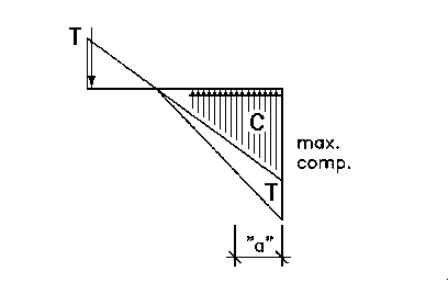
(Mot + Mwall) = (max. comp.)*(a)*(1.5)*(d-a)
"Constant" = (Mot + Mwall)/(max. comp. * 1.5)
a = (d - SQRT((d*d) - (4 * Constant)))/2
Tiedown = (max. comp.)*(1.5 * a) - (Weight of Wall)
NOTE: A maximum allowable compression must be assumed
before the hold-down force (also called tiedown) can be calculated.
For starters, use the allowable compression on a typical 2x wall stud
even though you might use a 4x post.
| Resulting Forces | |
 |
|
| The method on the previous page can be used to calculate
the resulting compression if a tiedown force is assumed. Because tiedown capacities are given by manufacturers, this method is often preferred by those designing shear walls. |
For lateral loads (triangular force pair)...
Mot = (Vroof * H) + (Vwall * H/2)
For vertical loads (rectangular force)...
Total Weight = (weight per foot * L) + TiedownMr = (Total Weight * L/2) + (Tiedown * d)
And finally...
"a" = (Mr-Mot)/(Total Weight)max. comp. = (2/3)*(Total Weight/a)
| Alternate Diagram | |
 |
|
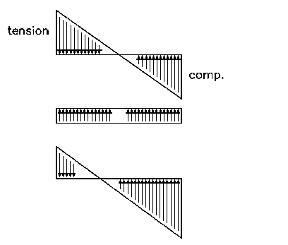
| Unlike previous diagrams, the compression is not simply
the sum of the wall weight...it now includes an amount equal to the force exerted by the tiedown. This maintains the balance between applied and resisting vertical loads. |