Collectors
A shear wall is only as strong as the load path leading
to it. Loads must be collected in other portions of the structure and delivered
to the top of the shear wall so they can be transferred into the plywood
sheathing. Often this is accomplished by means of the wall's double top
plate.
Double 2x plates are stacked, lapped and nailed together.
The number and size of nails determines the strength of the connection. In
rare instances - mostly where 2 x 4 plates are used - the strength of the
wood may have a bearing.
An example of a collector is presented below for your
reference. The steps used to calculate the maximum collector force are applicable
to similar elements constructed from beam segments or combinations of wood
and steel plates. The assumption is that the element that delivers load to
the collector is continuously connected to it ( a roof or second floor
).
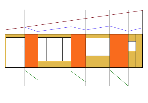
| Example of a
Collector |
 |
 |
 |
The wall sections that resist shear are shaded orange.
All other sheathing is tan.
The total building length is 45 feet. The walls are, from left to right,
4 feet, 5 feet and
6 feet long. The window regions, from left to right are 6 feet, 12 feet,
8 feet and two
feet with a 2 foot long segment of wall at the right. The total shear force
in this wall
line is 4500 pounds. |
|
The total lateral force "F" is apportioned to walls A
(at left), B (in center) and C (at right) according to their length. The
2 foot long wall at the far right does not meet the minimum width criteria
set by the current Code. Total useful wall length = 15 feet.
Force to wall A = (4500)(4/15) = 1,200 lbs.
Force to wall B = (4500)(5/15) = 1,500 lbs.
Force to wall C = (4500)(6/15) = 1,800 lbs.
Note these are all equal to 300 pounds per foot. Think
of the walls as removing 300 pounds per foot from the system. The negative
slope of the green lines above indicate loads are being removed load from
the wall system.
The force delivered to the collector is (4500)/(45)
= 100 pounds per foot.
Note that the red line above has a positive slope. It
indicates load is being contributed to the system.
The blue line represents the net collector force at any
point along the wall length. It slopes down at 200 pounds per foot in the
wall regions and climbs at 100 pounds per foot in the window regions. The
collector force can be read from a scale graph of these slopes or calculated
as follows:
-
Starting at the left, the force in the collector is zero.
But force builds up over 6 feet until we enter the first wall region. The
collector force at this location is (6)(100) = 600 pounds.
-
Over the next 4 feet we will continue to add 100 pounds
per foot for a total of 1000 pounds but we will also be deducting 300 pounds
per foot (-1200 lbs.). The net result at the right edge of the 4 foot shear
wall is a collector force of -200 pounds.
-
To continue, we will add 100 pounds per foot for 12 feet
for a net collector force of +1000 pounds.
-
In the next 5 feet we will add 500 pounds but also reduce
by 1500 pounds leaving a net collector force at the right edge of zero
pounds.
-
The remainder are: +800, -400.
We would design this collector line to resist a maximum
force of 1000 pounds. Using 16d common nails…
(1000 lbs.) / (141 * 1.33 * (1.5/1.78)) = 6.33 nails
>> Use 7-16d's minimum staggered and spaced 4" o.c.
If you would like to try your hand at collectors, use
the same forces as above but eliminate wall B.