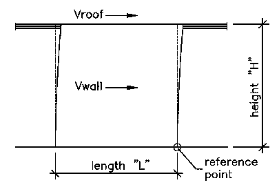
to the actual shear-resisting material.
When the applied load is small, the overturning moment is small, and the tendency for the wall to overturn is small. It may be that the weight of the wall panel itself counterbalances the system without the need for additional connections. The ability of a wall to resist overturning is calculated similar to the overturning moment by placing the sum of the wall weight at a distance away from the common point of overturning. This weight at a distance creates a moment, specifically the resisting moment. One moment wants to push the wall over, the other resists it.
| Basic Shear Wall Diagram | |
 |
|
| This first example is for walls with low shear loading
without regard to the actual shear-resisting material. |
Mot = The Overturning Moment. This value includes all loads that want to push the wall in a clockwise direction relative to the reference point position.Mr = The Resisting Moment. This value includes all loads that want to push the wall in a counterclockwise direction relative to the reference point.
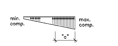
| Resulting Forces | |
 |
|
| The triangular force pair is the result of lateral
loads applied at a distance above the reference point (also see bottom of page).
The uniform horizontal compression force represents the
weight of
The two force diagrams can be added together to obtain
the |
For lateral loads (triangular force pair)...
Mot = (Vroof * H) + (Vwall * H/2)
For vertical loads (rectangular force)...
Mr = (Total Weight * L/2)
And finally...
"a" = (Mr-Mot)/(Total Weight)max. comp. = (2/3)*(Total Weight/a)
| Alternate Result | |
 |
|
| When "a" is greater than (L/3), the following formulas
should be used: max. comp. = (4L-6a)(W/(L*L)) |
The triangular loading pattern may be confusing at first. It may help to look at a similar result in a familiar system...
| Bending in a Beam | |
| The section of beam above shows the forces that result
from applied loads which cause the beam to bend. Tension forces come from the stretching of the wood fibers on the side opposite to the applied loads. Compression forces are generated by fibers being forced together at the loaded side. This matching and opposite pair of triangular forces is a typical result for materials subjected to bending. |
The "bending moment" in the beam is the total of the compression and tension forces times the distance to the centerline of the beam.
MOMENT = [(depth/2)*(2/3)]*[(max. force)*(depth/2)*(1/2)]*[2]
- [(depth/2)*(2/3)] = moment arm
- [(max. force)*(depth/2)*(1/2)] = total force
- [2] = two triangles